I have never liked diffraction spikes, they indicate artifacts across the entire field of view, both seen and unseen.
This was my attempt to solve the issue:
Design 201910056 | IP Australia | Australian Design Search
I designed this for my grandson, who has since died from meningitis along with any interest on my part to finish it. I had registered the design without considering the possibility that it was patentable. Which it was, until I registered it and had it certified. However, the design does have a flaw in it, but I have redesigned it so that it is patentable again. But my interest is still not present.
I have attempted to finish it, but also found it had a negative impact on my overall mental health.
Not being able to switch off my imagination led to the subject of this post.
I have a proof of concept image, which I posted in the EAA group. The image quality is irrelevant and is an effective filter of people who understand what they are seeing and those who don't. Did I mention it is out of focus, which revealed a mistake in a calculation I made to build the device. From failure comes success, etc.
With the success of the first light image, I have the protype designed with R.A. & DEC, polar alignment and tracking. The only sticking point now is getting time on the machines at work I need to use to make the parts. The design does not use the bucket method and is not bound by Dawes limit. Also, it is full aperture, unobstructed and does not use any refractive elements. The incident light has a clear path from the primary element to the sensor.
Unless you are willing to pay for a patent, I cannot give any more details.
But I will be posting the images on this site only and look forward to some clarity.
I am not sure how a critique can be given at this point, but that's Heisenberg for you.
|
You cannot like this item. Reason: "ANONYMOUS".
You cannot remove your like from this item.
Editing a post is only allowed within 24 hours after creating it.
You cannot Like this post because the topic is closed.
This is the only relevant update:
Project available for download.
The camera used is only a Hayear HY-500B, but it is sufficient for this project.
This is the program used to create the final videos:
ImageExtractor06.txt
These are the current results:
blue_channel_video.mp4
green_channel_video.mp4
red_channel_video.mp4
The image is an improvement, but I clearly need to work on the rigidity and the centrality of the 1mm aperture.
Whether or not it will help me build the final iteration remains to be seen.
|
You cannot like this item. Reason: "ANONYMOUS".
You cannot remove your like from this item.
Editing a post is only allowed within 24 hours after creating it.
You cannot Like this post because the topic is closed.
The final design has been decided with which to test the theory and a formula to describe the concept. I don't have the resources to build constantly improving iterations, I have the offcuts at work and a 420mm OD deep groove bearing from the bin. The bearing will form the base of the main stage that is polar aligned to provide tracking.
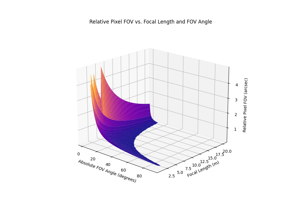
Concept of Relative Pixel FOV: Relative Pixel FOV is calculated based on the pixel size of the camera sensor and the effective focal length of the device. It represents the angle in arcseconds that a single pixel covers on the sky. A smaller relative pixel FOV indicates higher spatial resolution, allowing finer details to be captured in images.
Relative Pixel FOV (arcsec/pixel)=2×atan(Pixel Size (microns)/(2×Focal Length (mm))×3600
I have an issue with procrastination and have therefore imposed a deadline of June 30th, 2025. Why, why not!
The final device is still based on pinhole theory, just in a considered way. The primary element will be a 1/20th wave, pinhole sized diameter, that converts any light entering the system into incident light with a fixed absolute FOV. The platform anchored to the main bearing contains 20 secondary aluminum reflectors, with each adding 500mm to the total focal length and a proportional reduction in relative pixel FOV. The primary has the option of being coated with different materials to effectively provide an unobstructed form of wavelength filtration without affecting the source light using optical components.
The primary targets, once built and calibrated, will be the 20 closest I can see from my location. With M92 being of interest, with the Pop 3 potential. With the device configuration, measuring spectra is just a sensor module swap over.
I would apologize for any errors in the formula or theory, but it could be intentional, so I won't. 
Stay warm.
Paul
|
You cannot like this item. Reason: "ANONYMOUS".
You cannot remove your like from this item.
Editing a post is only allowed within 24 hours after creating it.
You cannot Like this post because the topic is closed.
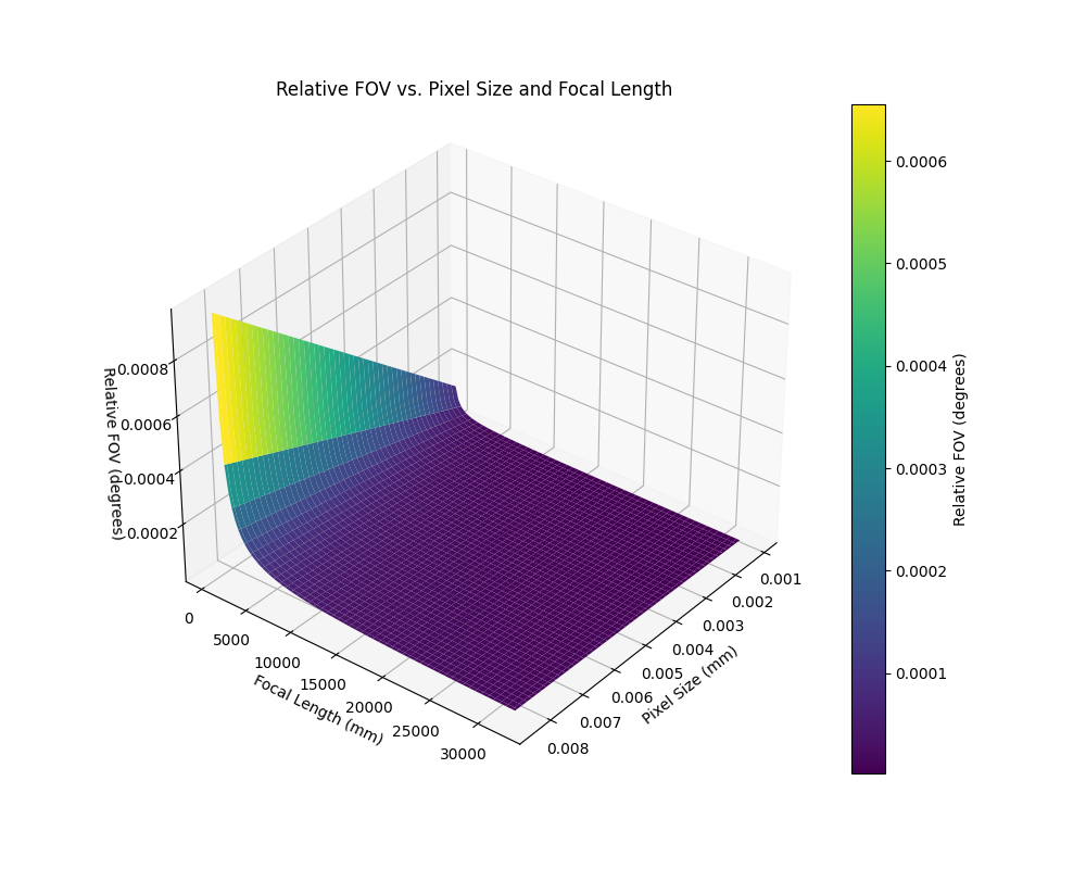
The following are 3D plots made using the formula posted recently to show the relationship between pixel size and relative FOV.
With the device to test this theory.
PolarPlatform02.pdf
Stay warm.
Paul
|
You cannot like this item. Reason: "ANONYMOUS".
You cannot remove your like from this item.
Editing a post is only allowed within 24 hours after creating it.
You cannot Like this post because the topic is closed.
to create to post a reply.